 Switch
Overview
Use this operator to switch a channel bus to one of two output channel buses. The switch is controled by the Gate input, which must have 1 channel.This operator is the counter part of the Switch Converge operator ("Switch Converge").
The Gate input expects a pseudo-boolean signal, which is either around 0 or around 1.
Operator ports
Input S: Any sample type. The connection is not limited to one type of signal.Input Gate: Floating point values
Output Sa: Any sample type. The connection is not limited to one type of signal.
Output Sb: Any sample type. The connection is not limited to one type of signal.
Properties
Find more information about changing properties here: "Properties Viewer"Irregular Capture
type: True or FalseIf the Switch is used to capture single samples from a stream, then you may need to set this flag to True to get a non-uniform output. Reconnect before the setting takes effect.
Select one of those presets:
True or False
True may also be read like 'yes' and false like 'no'
True or False
True may also be read like 'yes' and false like 'no'
You can use the Switch to capture single values from a continuous signal. Because those captures are not performed with a defined sample frequency, the sample rate at the output of the Switch is not correct.
If you later re-combine the two outputs of the Switch using a Switch Converge ("Switch Converge"), then this is not an issue. This property may be set to False.
However, if you would like to further process the capured single samples, you may need to tell the system that the output is non-uniform (non-equidistant samples). In that case, this property should be set to 'True'.
If you set this property to 'True', then the outputs both show a 'NON-UNIFORM' sample rate. Note: you must reconnect the input after changing this propery in order to take effect.
Read more in the detailed description of the Switch operator, or see "Timing properties of samples in a stream".
Note: this feature exists since Polybench 1.34
Caption
type: Word or phraseThe name of the object in the project. This name must not contain '.', '$' nor '@' characters.
For more information about the rules and usage of the Caption property, please refer to "Caption property - background and usage".
Documentation
type: See descriptionOptional documentation of this object. If this object is an operator, the Documentation text is displayed below the operator symbol.
Details
General working
The Gate input always functions as scalar. The Gate is connected to only one input channel, which switches all channels from S to either Sa or Sb at the same time.If the signal on the Gate input is less than 0, the Gate is set to 0. If it is greater than 1, it is set to 1. If the signal value is between 0 and 1, the value is rounded to either 0 or 1.
Therefore it is important to note that the Gate input signal should be a pseudo-digital signal, because if it contains a slow rizing signal, the switch timing is difficult to predict.
Switch and Switch Converge
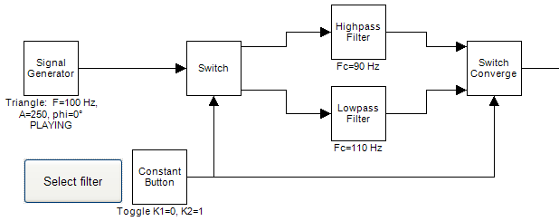
The schematic below shows an example of the Switch and "Switch Converge", that together form the equivilent of what in other computer languages would be called IF..THEN..ELSE. Using the constant button either the high pass filter, or the low pass filter is selected.Note that at the output of the Switch Converge, time timeline is continued, but the mathematical properties of the signal may be broken.
Switch breaks the time line
The outputs of the Switch will be signals of which the time line can be broken. For example, if you switch the input signal 10 seconds to the second output, then the time line of the first input will show a hole of 10 seconds.Y-T Viewers, but also signal data storage files may have a problem with that. Please thoroughly check the schematic behind a switch if there are no unforeseen problems because of this.
On the other hand, the breaking of the time line may also deliberately be used. You could write an application that picks single samples (by switching the Switch one sample period of time) from a signal and displays them in a X-Y Plotter, or stores them in a CSV file. Most math operators won't have a problem with signals with broken time lines, so you could do calculations on the 'picked' samples.
This way, you can record results of culculations at specific moments in time. The next picture shows an example of this:
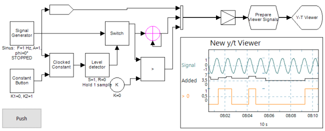
The example shows, that samples that are captured at irregular intervals can be merged with a normal data stream and then shown in a Y-T Viewer. This is only possible because the Irregular Capture property is set to True. The output of the Switch so 'officially' becomes a non-uniform sample stream that can be connected to the Channel Merger (see also "Timing properties of samples in a stream").
It is important to understand that only the Channel Merger and the Synchronizer will favour the regular sample stream, so that the non-uniform samples are converted to a time signal again. All other operators will only update at the speed of the non-uniform samples, as is depicted in the next image:
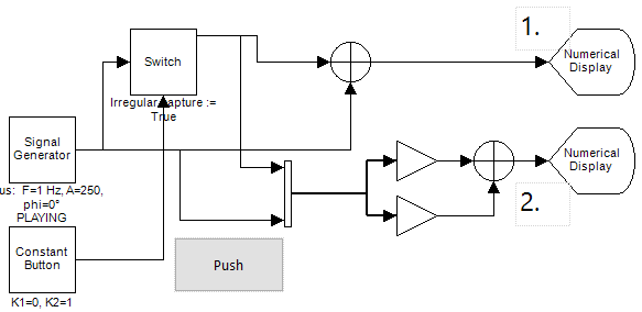
1) Samples only stream when the button is pushed, because the Adder waits for the non-uniform samples from the Switch. 2) Samples flow continuously, because the Channel Merger takes the sampling frequency of the Signal Generator, and the non-uniform samples from the Switch are merged into the signal by over-sampling them.
Notice the difference in using the Switch to capture single samples and the Sample and Hold operator ("Sample & Hold") to do similar things. Using the Switch, the captured sample is only one sample, whereas using the Sample and Hold, the captured values are repeated at the sampling frequency until the next values are captured. Using the Switch, for example, it is easier to calculate the mean of captured values, as shown in the next image:
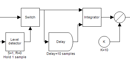
Mean over the last 10 (irregularly) captured single values
Examples
Example: Switch demo
Example of the use of the Switch operator. The Switch switches the input signal to one of both viewers, depending on the state of the Constant Button.Examples\DF0411131_001_Switch Demo.xmc
Example: Switch nonuniform capture demo
Demonstrates how the Switch operator is used to capture samples at irregular intervals, do operations on those non-uniform samples, and merge those samples with a sample stream again.Note that the Level Detector is used to get a 'one-shot' pulse from the Constant Button. This way, it doesn't matter how long you press the button; the pulse will always be one sample long.
Examples\DF0411131_002_Switch_Nonuniform_Capture_Demo.xmc