 EDF+ File Format provider
Overview
Reads files with file header EDF+ SAMPLE FILEversion 2004 and writes EDF+ files (ver. 2004) in 16 bit resolution, with or without annotations.Details
Settings
This stream interface offers settings that specify how the interface should work. Those settings are available in the properties dialog as well as in variable parameters.Physical range
Default value: 1(-100/100);2(-100/100);3(-1000/1000);
Defines the physical minimum and maximum in units of the physical dimension. Format: n(x/y);n+1(x/y); where n = channel number (starts with 1), and x/y means x = min and y = max. Some known channel names (e.g. EOG) may lead to a special automatic default range, to get the default min/max for that channel name (see manual). You may write ALL(x/y) to specify all channels to have a range; and RANGE[a/b](x/y), to let channel a until b have the specified range.
Transducer type
Default value:
Defines the transducer type of the electrode. Format: n(T);n+1(T); where n = channel number (starts with 1), and T = transducer type text (e.g. AgAgCl electrode). Use ALL(T) to set the same text for all channels. Use RANGE[a/b](T) to set the text for channel a until b.
Prefiltering
Default value:
Defines the prefiltering of each channel. Format: n(P);n+1(P); where n = channel number (starts with 1), and P = prefiltering text (e.g. HP:0.1Hz LP:75Hz). Use ALL(P) to set the same text for all channels. Use RANGE[a/b](P) to set the text for channel a until b.
IncludeEvents
Default value: YES
Set to YES if event markers in the signal should be stored into the file as annotations, or NO if they should not be. The events will still be saved in a separate CSV-file.
Events Space
Default value: 100
Set the space into the file for annotations in digital words of 2 bytes. By default 100, which in a standard situation is enough for over 100 characters for event codes per second. Minimal value is 8. If you take this value too small, not all annotations can be stored! If that happens, the last annotation of a data block will be '!'.
Description
If you want to record using this well known file format, then you have to consider two important things:1. The format stores sample values in only 16 bit width. Polybench works with 64-bit values. In order to get the Polybench samples into the EDF+ file, the values are scaled so that they fit in the EDF+ format, as is described by Bob Kemp et al. in their EDF file format specification. As a result, the samples that you read from an EDF+ file may have a small deviation from the original values, because the resolution of the values have become smaller.
You have to specify yourself how the signals need to be scaled, because an optimal scaling depends on the range in which your signal is moving. You can specify this in the Storage operator (link) properties, after you have selected the EDF+ file format. The signal range has to be specified for every channel (or you may define all channels having an equal range).
Note that if you take the range too large, that you get a very bad resolution of your signal (your signal may even dissolve and look like a zero-signal afterwards). If you take the range too small, then signals that exceed the range are cut off! So, if you specify the physical range 1(-1000/1000); and your signal on channel 1 get higher than 1000, then in the file the signal will be cut off to the value of 1000.
2. Event markers (called annotations in EDF+) need space that you have to specify in advance. In the Storage operator you specify the Event Space. If that value is too small to hold all event markers in a section of the signal (for example in one second worth of samples), then some annotations will get lost! If that happens, the last annotation of that section will become '!'. So if you see the annotation '!' you know that originally there were more event markers, but they have not been saved inside the EDF+ file. They do have been saved in the event CSV file, so you won't loose them completely.
Full specification of EDF+
The original article about this file format was published by Elsevier and provides some background information and examples:An extension of EDF, named EDF+, was developed in 2002 and is largely compatible to EDF. All existing EDF viewers also show EDF+ signals. But EDF+ files can also contain interrupted recordings, annotations, stimuli and events. Therefore, EDF+ can store any medical recording such as EMG, Evoked potentials, ECG, as well as automatic and manual analysis results such as deltaplots, QRS parameters and sleep stages. The specs are stricter than EDF which enables automatic localization and calibration of electrodes. And EDF+ fixed a few major (Y2K problem, little-endian integers, comma vs dot) and minor omissions in EDF.
EDF+ was published in 2003 in Clinical Neurophysiology 114, pages 1755-1761. Since then, hundreds of EDF+ files and several EDF+ viewers became available on the internet. Applications till now are mainly in Clinical Neurophysiology, Sleep, and Cardiology. Formal standards from other specialisms can also be integrated into EDF+.
The following texts are copied from Bob Kemp, Alpo Vaerri, Thomas Penzel, Jesus Olivan.
Introduction
The use of standard texts in several EDF+ fields is useful if it facilitates more automatic and reliable data processing. This page specifies standard texts that correspond to widely accepted definitions in Clinical Neurophysiology, such as the 10/20 and 10/10% electrode systems. The texts are obligatory in EDF+.The signal fields 'label' and 'physical dimension'
Standard texts for the EDF+ header fields 'label' and 'physical dimension' enable EDF+ software to automatically recognize the kind of signal (EEG, EMG and so on), its polarity and dimension, and the location of sensors (such as EEG electrode positions for mapping). These standard texts comply with the EDF specs and therefore do not cause any incompatibility with EDF software. The texts are obligatory in EDF+ but not in EDF.The standard 'label' structure
The header field 'label' offers 16 ASCII characters. The standard structure consists of three components, from left to right:- Type of signal (for example EEG).
- A space.
- Specification of the sensor (for example Fpz-Cz).
As in all fields, this standard text must be left justified in the 16-character field and then filled out with spaces. In this example, the standard label reads 'EEG Fpz-Cz '. Further possibilities are listed in the signals table below.
The standard 'physical dimension' structure
The header field 'physical dimension' offers 8 ASCII characters. The standard structure that we propose here consists of two components, from left to right:- Prefix (for example u).
- Basic dimension (for example V).
As in all fields, this standard text must be left justified in the 8-character field and then filled out with spaces. In this example, the standard physical dimension reads 'uV ', that is microvolt (note the use of a standard-ASCI 'u' rather than the forbidden non-standard-ASCII 'mu' character). Further possibilities are listed in the signals table below.
Powers in a basic dimension (for instance the basic dimension of a volume is: meters to the power 3) are noted by ^. Examples are m^3 for a volume or m/s^2 for acceleration. Some basic dimensions involve more complicated mathematical expressions, such as for instance in Kg*m/s^2. Of course, first everything between brackets must be evaluated. Then the evaluation order is: prefix - powers - multiplication - division. In this example, the evaluation is ((Kg)*m)/(s^2). As another example, Km^2 means (1000m)^2, not 1000(m^2).
These 16- and 8-character fields contain the standardized information about the type of signal and its dimension. Further, non-standardized, information can be stored in the 80-character fields 'Transducer Type' and 'Prefiltering'.
List of signals with the corresponding label and dimension
The standard 'label' contains a 'Type' of signal and a 'Specification' component. The standard 'physical dimension' contains a 'Basic' dimension component that can be preceded by a prefix. The prefix multiplies or divides the basic dimension by factors of 10 until 10^24. Standard prefixes are listed below.As an illustration of the versatility of EDF and EDF+, the table also shows some signals that have not yet been, but can easily be, stored. In fact, any time-varying signal, from geology to medicine or the stock market, can be stored.
             Signal                Label (16 ascii) 	                         Physical Dimension (8 ascii)
                                   Type  Specification Example                Basic           Example
             Length or distance    Dist  any           Dist A'dam-R'dam       m               km
             Area                  Area  any           Area pupil             m^2             mm^2
             Volume                Vol   any           Vol moon               m^3             mm^3
             Duration              Dur   any           Dur AP                 s               ms
             Velocity              Vel   any           Vel light              m/s             mm/s
             Mass                  Mass  any           Mass body              g               mg
             Angle                 Angle any           Angle azimuth          rad, deg        deg
             Percentage            %     any           %                      %               %
             Value (money)         Value               Value                  (see below)     NLG

             Electroencephalogram  EEG   (see below)   EEG Fpz-Cz             V               uV
             Electrocardiogram     ECG   (see below)   ECG                    V               mV
             Electrooculogram      EOG                 EOG horizontal         V               mV
             Electroretinogram     ERG                 ERG left               V               uV
             Electromyogram        EMG   (see below)   EMG LAT                V               mV
             Magneto encephalogram MEG                 MEG
             Magneto cardiogram    MCG                 MCG
             Evoked Potential      EP    (see below)

             Temperature           Temp  any           Temp rectal            K, degC or degF degC
             Respiration           Resp  (see below)   Resp abdomen
             Oxygen saturation     SaO2  any           SaO2 finger            %
             Light                 Light any           Light sternum
             Sound                 Sound any           Sound trachea
             Events                Event any           Event button
Specifications and polarity rules for EXG labels
The 'Specification' of an EEG, EP or EMG signal consists of the locations of the two recording electrodes, separated by a '-' (minus) character. The voltage (i.e. signal) in the file by definition equals [(physical miniumum) + (digital value in the data record - digital minimum) x (physical maximum - physical minimum) / (digital maximum - digital minimum)]. This voltage must equal the potential at the first electrode (before the '-' character) minus the potential at the second electrode. For example, if the 'Specification' is Fpz-Cz (i.e. the standard label reads 'EEG Fpz-Cz '), then the voltage in the file must be the potential at Fpz minus the potential at Cz. In case of a concentric needle electrode recording, a positivity at the centrally insulated wire relative to the cannula of the needle is stored as a positive value in the file.If electrodes are on any of the below-mentioned standard locations then the corresponding names must be used, for instance in 'EEG Fpz-Cz '. Otherwise any other name is appropriate, like in 'EEG A-B '. If the electrode locations cannot be accurately specified in short form, like in some EMG recordings, the 'Specification' may be replaced by a less accurate indication such as the name of the muscle.
In many standard procedures in Clinical Neurophysiology, a relative negativity at the first electrode must be displayed as an upward deflection on the screen. The displaying software must implement any such 'negativity upward' rule by simply upwardly displaying a negative voltage in the file.
In standard EEG investigations, EEG electrode signals in the file are usually referenced to one, common, electrode, for example A1. The file then contains, in this example, the signals C1-A1, C2-A1, C3-A1, C4-A1, F1-A1, F2-A1, F3-A1, and so on. This enables re-referencing (remontaging) of derivations afterwards and reduces file size. In some cases, the reference electrode is an average over more than one electrode. In that case, define this average between round brackets. For instance, the EEG between C3 and linked earlobes has label 'EEG C3-(A1+A2)/2'. If the reference is unknown, irrelevant (for instance because it is only used temporarily), or makes the signal label exceed its 16 characters, then use the text Ref, for instance in 'EEG C3-Ref '. If more of such references exist, then use the text Ref1, Ref2, and so on.
The two EMG derivations for leg movement scoring, as described in the 2007 "AASM manual for the scoring of sleep and associated events", have specifications "RAT" and "LAT" for the right and left anterior tibialis muscle, respectively. So, the standard labels are "EMG RAT" and "EMG LAT".
If a standard ECG derivation I, II, III, aVR, aVL, aVF, V1, V2, V3, V4, V5, V6, or -aVR, or V2R, V3R, V4R, V7, V8, V9, or X, Y, Z is recorded, then the 'Specification' of the ECG signal must equal the name of that derivation, for instance resulting in label 'ECG V2R '.
Specifications for respiration labels
chest abdomen oral nasal oro-nasal
For example, the standard label for a nasal airflow recording is 'Resp nasal '. The 'Transducer type' field should make clear whether this was a pressure, thermistor or thermocouple recording.
Dimension prefixes and EEG electrode names
Left section of table: dimension prefixes that multiply or divide the basic dimension by factors of 10 till 10^24. For example, the dimension uV means microVolt (10^-6 Volt, that is 0.000001 Volt), ms means millisecond and Ms means Megasecond. Note that the prefix 'u' is the standard-ASCII letter 'u', not the extended-ASCII letter 'µ'. Middle section: standard locations for EEG electrodes according to the international 10/20 and 10/10% systems. For instance C3 denotes the Central-left electrode at position 3. Right section: the standard basic dimension for a currency equals the standard abbreviation as used by banks.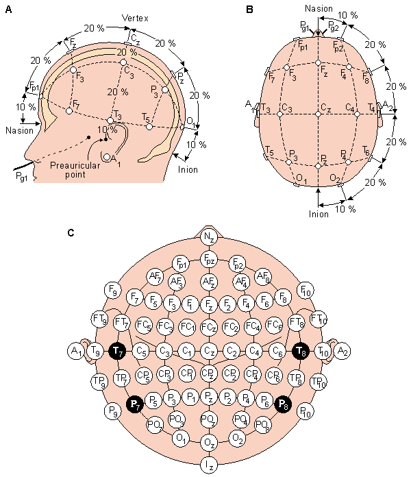
Figure: The standardized 10/20 (top) and 10/10% (bottom) electrodesystems. Note that the T3, T4, T5 and T6 electrodes of the 10/20 system have different names (T7, T8, P7 and P8, respectively) in the 10/10% system. Figure from the webversion of the book by Jaakko Malmivuo and Robert Plonsey: Bioelectromagnetism - Principles and Applications of Bioelectric and Biomagnetic Fields, Oxford University Press, New York, 1995", chapter 13.3.
Annotations
Standard 'Annotation' texts enable EDF+ software to automatically detect apneas, leg movements and so on. They are obligatory in EDF+ and do not apply to EDF. The texts speak for themselves.General Annotations
Annotations mainly for PSG scoring
Note that all annotations except the top row must also specify a duration.Added in accordance to recommendations of the AASM2007 manual were the Periodic limb movement of sleep (PLMS), Sleep stages N/N1/N2/N3, Respiratory events including Cheyne Stokes breathing (CS breathing), Cardiac events, Bruxism, REM sleep behavior disorder (RBD), and Rhythmic movement disorder (RMD).
Note that the R+K1968 sleep stages 1, 2, 3, and 4 cannot be used when scoring according to the AASM2007 manual. Use the new stages N, N1, N2 and N3 instead.
Note that a limb movement is annotated as 'Limb movement' and not as 'LM'.
The full list:
             Lights off         Lights on

             Sleep stage W      Sleep stage 1        Sleep stage 2      Sleep stage 3
             Sleep stage 4      Sleep stage R        Sleep stage ?      Movement time
             Sleep stage N      Sleep stage N1       Sleep stage N2     Sleep stage N3

             Apnea              Obstructive apnea    Central apnea      Mixed apnea
             Hypopnea
             Hypoventilation    Periodic breathing   CS breathing       RERA

             Limb movement      PLMS
             EEG arousal

             Sinus Tachycardia  WC tachycardia      NC tachycardia   Bradycardia
             Asystole           Atrial fibrillation

             Bruxism            RBD                 RMD
HEADER RECORD
                   8 ascii : version of this data format (0)
                  80 ascii : local patient identification (mind item 3 of
                             the additional EDF+ specs)
                  80 ascii : local recording identification (mind item 4 of
                             the additional EDF+ specs)
                   8 ascii : startdate of recording (dd.mm.yy) (mind item 2
                             of the additional EDF+ specs)
                   8 ascii : starttime of recording (hh.mm.ss)
                   8 ascii : number of bytes in header record
                  44 ascii : reserved
                   8 ascii : number of data records (-1 if unknown, obey
                             item 10 of the additional EDF+ specs)
                   8 ascii : duration of a data record, in seconds
                   4 ascii : number of signals (ns) in data record
             ns * 16 ascii : ns * label (e.g. EEG Fpz-Cz or Body temp) (mind
                             item 9 of the additional EDF+ specs)
             ns * 80 ascii : ns * transducer type (e.g. AgAgCl electrode)
             ns *  8 ascii : ns * physical dimension (e.g. uV or degreeC)
             ns *  8 ascii : ns * physical minimum (e.g. -500 or 34)
             ns *  8 ascii : ns * physical maximum (e.g. 500 or 40)
             ns *  8 ascii : ns * digital minimum (e.g. -2048)
             ns *  8 ascii : ns * digital maximum (e.g. 2047)
             ns * 80 ascii : ns * prefiltering (e.g. HP:0.1Hz LP:75Hz)
             ns *  8 ascii : ns * nr of samples in each data record
             ns * 32 ascii : ns * reserved
DATA RECORD
             nr of samples[1] * integer : first signal in the data record
             nr of samples[2] * integer : second signal
             ..
             ..
             nr of samples[ns] * integer : last signal
Typical settings of the physical limits of the signals
             Application    min. value    max. value
             BIP            -100 uV       100 uV
             DIG               0           32
             EAG            -100 uV       100 uV
             ECG            -100 uV       100 uV
             EEG              50 uV       -50 uV
             EGG            -100 uV       100 uV
             EMG            -100 uV       100 uV
             EOG            -125 uV       125 uV
             ExG            -100 uV       100 uV
             FLOW           -180 l/min    180 l/min
             FiO2             21 %        100 %
             Hypnogram      -0.9          6.9
             Pulse            30 BPM      250 BPM
             SaO2             75 %        100 %
             Saw             -64           64
             SpO2             90 %        100 %

             Defaults range settings are min. = -1000 and max. = 1000, if
             the signal is not as called above.