 Synchronizer
Overview
The Synchronizer is an important operator in case you are using multiple data sources. Different data sources are not guaranteed to have equally distributed sample periods, and also they may use different burst modes. The Synchronizer takes care that the different sources are synchronous. Also it converts all input buses to the same sample frequency, which is the highest of the input buses.Operator ports
Input Any1: Any sample type. The connection is not limited to one type of signal.Input Any2: Any sample type. The connection is not limited to one type of signal.
Input Any3: Any sample type. The connection is not limited to one type of signal.
Input Any4: Any sample type. The connection is not limited to one type of signal.
Input Any5: Any sample type. The connection is not limited to one type of signal.
Output Any1: Any sample type. The connection is not limited to one type of signal.
Output Any2: Any sample type. The connection is not limited to one type of signal.
Output Any3: Any sample type. The connection is not limited to one type of signal.
Output Any4: Any sample type. The connection is not limited to one type of signal.
Output Any5: Any sample type. The connection is not limited to one type of signal.
Properties
Find more information about changing properties here: "Properties Viewer"Caption
type: Word or phraseThe name of the object in the project. This name must not contain '.', '$' nor '@' characters.
For more information about the rules and usage of the Caption property, please refer to "Caption property - background and usage".
Documentation
type: See descriptionOptional documentation of this object. If this object is an operator, the Documentation text is displayed below the operator symbol.
Details
The Synchronizer has 5 inputs and 5 outputs. These inputs and outputs are mirrored, that is input S1 connects to output S1, input S2 to output S2, etc. The channel information is copied unchanged to the output(s).Not all inputs have to be connected for the Synchronizer to work. You can choose to connect as many inputs as you need. Connected inputs are allowed to have different numbers of channels.
Constant, control and messaging operators cannot be connected to the inputs. If such operators are connected, the Synchronizer will issue a warning and stop working. Note that constants do not need to be synchronized, because they do not have a special timing. See also "Timing properties of samples in a stream".
It is allowed to connect non-uniform signals (signals that do not have a regular sample period interval), but only if at least one timed signal is also connected. The non-uniform signals will then be aligned with the timed signal, and the outputs will show the sample rate of the timed signal.
For each timed sample, the last non-uniform sample is put through, so if the timed signal's sample rate is lower than the update rate of the non-uniform signal, you may loose non-uniform samples.
All outputs get the same sample rate, which is the highest of all connected inputs. If one or more sources do not output samples, because they have not been started, the Synchronizer does not output samples either.
The Synchronizer supports sample bursts of maximally 10 seconds. This means, that if a data source puts out a burst of samples, this burst should not contain more than 10 seconds worth of samples. For very low frequency signals (< 1 Hz) at least 10 samples are buffered.
The synchronizer will cause a delay between input and output. The delay time is undefined, because it depends on the burst size of the input sources. For example, if a device outputs data in bursts of 0.5 seconds worth of samples, then the delay time will be just over 0.5 seconds. There will be no delay difference between each output.
Feedback from a bus from one of the outputs of the Synchronizer is not allowed, but this may not be made clear by the designer. If you do make a feedback loop involving the Synchronizer operator, this may lead to undefined effects or bad performance.
Data sources from hardware devices need to be set to Synchronized mode
If a signal at one of the inputs stems from a hardware device operator, then that device operator must be set to Synchronized mode. All hardware device operators that contain the Synchronized property, must have their Synchronized property set to True. Read more about synchronizing different devices here: "Synchronization of multiple data sources".If Synchronized is set to True on hardware device operators, this specifies that the data acquisition is System Synchonized, as opposed to Device Synchronized. To be able to combine signals from different hardware signal sources, all sources require to be System Synchronized. Signal sources such as from the Signal Generator ("Signal Generator") are controled by the system and are therefore automatically System Synchronized. If a hardware device operator is not set to Synchronized mode, the Synchronizer operator will show a buffer overflow after some undefined period of time. If this happens, the operator gives a warning below the symbol.
Examples
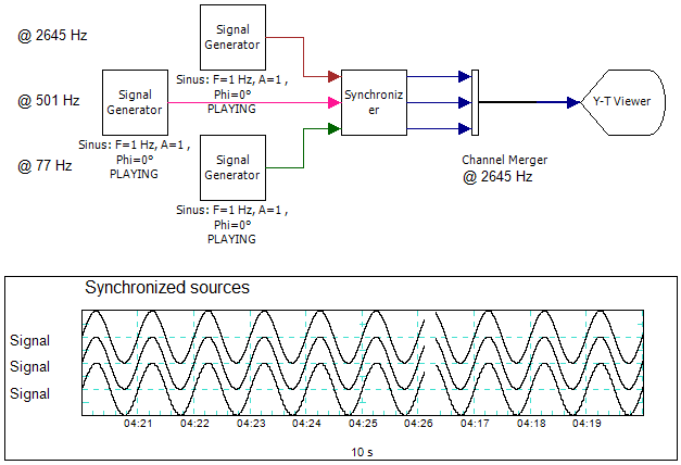
Example: Synchronizer Demo
Demonstrates various aspects and behavior of the Synchronizer operator.Examples\DF0308038_001_Synchronizer_Demo.xmc