 Epoch Buffer
Overview
This operator will generate a buffer or vector from streaming data. The incoming data will be placed into the buffer in a linear way; the first field will contain the first sample of data that came in, the second field will contain the second sample, and so on.When a trigger (more about trigger can be found here: "Pseudo-booleans and triggers") is detected on the trigger input, then the buffer is put to the output. After that, the operator starts with a new clean buffer.
Operator ports
Input S: Floating point valuesInput S_Trigger: Floating point values
Output V_buf: Floating point value buffers
Output V_mask: Floating point value buffers
Properties
Find more information about changing properties here: "Properties Viewer"BufferLength
type: Integer valueThe length of the epoch buffer at the output. If less samples are copied to the output buffer, then the rest of the fields in the buffer will be 0. Must be greater or equal to 1.
VectorOutput
type: True or FalseDetermine if the buffers at the upper output are just data buffers (false), or mathematical vectors (true).
Select one of those presets:
True or False
True may also be read like 'yes' and false like 'no'
True or False
True may also be read like 'yes' and false like 'no'
Many operators in Polybench can be used for data buffers as well as for mathematical vectors (describing points in a multi-demensional space). Some of the operators behave differently for buffers and vectors, therefore if you intend to do vector calculation, it is important to set this property.
Caption
type: Word or phraseThe name of the object in the project. This name must not contain '.', '$' nor '@' characters.
For more information about the rules and usage of the Caption property, please refer to "Caption property - background and usage".
Documentation
type: See descriptionOptional documentation of this object. If this object is an operator, the Documentation text is displayed below the operator symbol.
Details
The output buffer has a predefined size (property BufferLength). If a trigger is detected, but the buffer is not yet completely filled, then the last fields will stay 0.The second output of the Epoch Buffer outputs a vector with the same properties as the buffer at the first output. However, it does not contain the sample values from the input, but it contains 1 for every field in the buffer that was filled, and 0 for the fields that were not filled, because a trigger came before the buffer was filled completely.
If the buffer is full, and still no trigger is detected, then all input samples are ignored from that moment on.
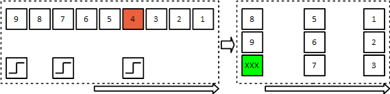
Explanation: The left rectangle shows 9 floating point samples and 3 trigger samples that arrive at the input of the Epoch Buffer operator. The Epoch Buffer is set up to put out buffers with 3 fields. The first trigger causes sample 1,2 and 3 to be copied to a buffer sample, shown in the right rectangle. Sample 4 is lost, because after sample 3 the current buffer was full. The second trigger copies the new buffer (containing accidentally the next three samples) to the output. The third trigger again copies a new buffer to the output, although that buffer is not yet full. Therefore the last field in the buffer becomes 0.
The second output of the Epoch Buffer operator, in this example, will put out a buffer with three ones; then again a buffer with three ones; and then a buffer with two ones and one zero.
Connection properties
The output of this operator does not have a sample frequency, because the output buffer samples have an irregular timing. This means that operators that are connected to the output of the Epoch Buffer do not have any information about when the buffer was created, in relation to the input signal.The Epoch Buffer functions like a data source. This means that you cannot merge signals from other sources (like other Epoch Buffers), without synchronizing the signals. Please note that you cannot synchronize just two Epoch Buffers, because it cannot be known when the operators output their data. Therefore, the Synchronizer operator ("Synchronizer") always requires at least one timed signal input.
Note that both outputs of the Epoch Buffer are actually synchronous, because their timing and size is exactly the same.
Buffers or vectors
In many cases this operator is used to create buffers of data for statistical purposes, but sometimes the buffers are interpreted as mathematical (complex) vectors, describing points in a multidimensional space. Those vectors use the same infrastructure as ordinary buffers, so there is almost no difference - except that some calculations are different for buffers and vectors.See the VectorOutput property to control this behavior.
Operators that behave differently for buffers and vectors will have extra notes in the manual that describe the way they handle vectors.
Example configuration
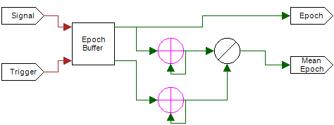
This configuration shows how the average over the epoch buffers is calculated. The mask output (containing a 1 for each valid buffer field) serves as a counter. Each field is divided by its own count, in order to get the mean of each field in the buffer.
Examples
Example: Epoch Buffer Example
The Epoch Buffer transforms streaming data into vectors lineairly. When the last field of the vector is filled, the operator will wait until a trigger, set a vector at the output and reset the buffer. The output is constant and does not have a frequency.Examples\DF0507019_001_EpochBuffer_Exmp.xmc
Example: Complex Epoch Exmp
This is a more complex example of how the epoch buffer can be used in combination with other Vector operators. On a push on the button, the buffer will be emptied and started over. The content of the buffer is put out. From this content, the peak is detected, and where the peak was, compared to the begin of the buffer.Examples\DF0507019_002_EpochBuffer_Exmp2.xmc
Example: Evoked Potential Example
This example shows how an evoked potential can be measured and extracted from a signal with noise.The signal consists of 4 signal generators, creating a waveform, and a noise generator, whos amplitude is about 3 times as big as the combined wave amplitude. By adding the different measurements who have the same waveform, the noise will cancel itself out, and the actual waveform can be recovered.
Examples\DF0507019_003_Evoked_Potential_Exmp.xmc