Buffer to Signal
Overview
This operator is a kind of opposite of the buffer operators, like Epoch Buffer and Circular Buffer. This operator converts a buffer or a vector back to a floating point type signal.Operator ports
Input V: Specific sample type, see below.Input S_def: Floating point values
Output S: Floating point values
Properties
Find more information about changing properties here: "Properties Viewer"OutputSampleFrequency
type: Real valueThe sample frequency at the output of this operator, in samples per second (Hz). The value -1 means constant value output.
Caption
type: Word or phraseThe name of the object in the project. This name must not contain '.', '$' nor '@' characters.
For more information about the rules and usage of the Caption property, please refer to "Caption property - background and usage".
Documentation
type: See descriptionOptional documentation of this object. If this object is an operator, the Documentation text is displayed below the operator symbol.
Details
Two modes of operation
The Buffer to Signal knows two modes of operation: One is timed, with timing based on the second input; the other is untimed, where the output signal does not relate to any timing in the system.Untimed mode
If the second input is not connected, then the Buffer to Signals operates untimed.In that case, the Buffer to Signal operator does not know the sample frequency of the original signal that was converted to buffers or vectors. Therefore you have to specify the output sample frequency yourself. In many cases you will specify the sample rate of the signal before it was captured by one of the buffer operators.
As soon as a new buffer or vector arrives at the input, all fields are put out as samples immediately. Although a sample frequency is specified, the output speed is uncontrolled. Therefore, in this mode you cannot combine the Buffer to Signal with any other signal source. Also, it does not help to connect the de untimed output to a Synchronizer ("Synchronizer"), because it cannot cope with uncontrolled timing.
You may use this mode to quickly calculate results from the buffer in the form of a signal.
Timed mode
If the second input is connected to a normal signal source (any source would do), then the output of the Buffer to Signal uses that signal as carrier.If no buffer or vector is available at the first input, then the input signal is copied to the output. As soon as a buffer arrives at the input, then each next signal sample is replaced by the next field of the buffer.
If then all fields of the buffer have been put out, the output signal continues to copy the input signal.
If the last buffer is being smeared out over the input samples, and then already a new buffer arrives at the first input, then the last buffer is discarded and overwritten by the new buffer. So, this operator does never store more than one buffer or vector.
Use case
Below is a schematic that uses the Buffer to Signal operator in untimed mode, to show the mean of a buffer as signal: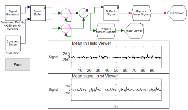
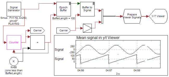
The next example uses the Buffer to Signal in timed mode. The Counter operator's output is taken as carrier (that is an arbitrary choice). The Epoch Buffer is triggered just in time to take the next 100 samples of the sinus and put it in a buffer. Because of this perfect timing, the buffers form a complete sinus again on the carrier signal.
If you would change K, then you will see that the sinus is not perfectly glued together anymore.