 Electrode Map
Overview
This viewer draws electrode images for every channel on a background object. The background may contain an image.During design time, but optionally also at end-user run time, the electrode positions can be changed.
Operator ports
Input Colors: Specific sample type, see below.Paired User Interface Object
This operator is loaded simultaneously with a user interface object. The user interface object can be moved to another page, and would normally be displayed in the end-user application. The operator and this user interface object can never be separated. If you delete the operator, the user interface is deleted automatically as well. Note that you cannot delete the user interface, only the operator symbol!Properties
Find more information about changing properties here: "Properties Viewer"ElectrodeSize
type: Integer valuedefault size of the electrodes in a value between 0 and 1000. 1000 means that the electrode would fill the entire map.
Editable
type: True or FalseSet to false if the user should not be able to move the electrodes on the electrode map
Select one of those presets:
True or False
True may also be read like 'yes' and false like 'no'
True or False
True may also be read like 'yes' and false like 'no'
BackgroundImage
type: Known image nameThe name of the background image. The image name can be selected from the Image Repository (press the small button).
This property uses the Image Repository. For more information about the use of images in a project, refer to "Image Repository"
ForegroundColor
type: Known color nameColor name from the color repository
This property uses the Color Repository. For more information about the use of colors in a project, refer to "Color Repository"
BackgroundColor
type: Known color nameColor name from the color repository
This property uses the Color Repository. For more information about the use of colors in a project, refer to "Color Repository"
ElectrodeDefaultColor
type: Known color nameDefault color for every electrode; this is a color name from the color repository
This property uses the Color Repository. For more information about the use of colors in a project, refer to "Color Repository"
BorderStyle
type: See descriptionBorder style from the border repository to define the outer border. Leave empty to have no border.
Font
type: Known text font nameNormal text font name from the font repository.
This property uses the Font Repository. For more information about the use of text fonts in a project, refer to "Font Repository"
TextPosition
type: Select from the listThe position of the text in relation to the electrode symbol it belongs to.
Select one of those presets:
Top
The text is displayed above the electrode
Right
The text is displayed right from the electrode
Bottom
The text is displayed below the electrode
Left
The text is displayed left from the electrode
Top
The text is displayed above the electrode
Right
The text is displayed right from the electrode
Bottom
The text is displayed below the electrode
Left
The text is displayed left from the electrode
Caption
type: Word or phraseThe name of the object in the project. This name must not contain '.', '$' nor '@' characters.
For more information about the rules and usage of the Caption property, please refer to "Caption property - background and usage".
Documentation
type: See descriptionOptional documentation of this object. If this object is an operator, the Documentation text is displayed below the operator symbol.
Extra dialog to change properties of this object: Default layouts
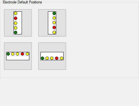
Details
The Electrode Map operator has a Color input, and not a signal input. To convert signals to colors, use the Signal to Color operator ("Signal To Color"), which provides a number of color schemes that can be used to color the electrodes on the map.After connecting the Electrode Map operator to the color signal, electrode symbols are displayed on one side of the map. You should then drag the electrodes one by one to the place you want them to have. To be able to drag the electrodes, the Editable property should be set to True.
A common use of the Electrode Map is to display the electrodes on positions on a background image. You can load a background image in the Image Repository, and then select that image in the property BackgroundImage.
The size of all electrodes can be changed. Used is a sizing scale between 0 and 1000, where 0 is invisible and 1000 for filling up the entire map area. If you change the size of the entire map, you will see that the electrodes scale. This is because there size is relative to the map size.
The properties dialog of the Electrode Map offer functions to align the electrodes along the left, top, right or bottom border of the map. You will probably have to select an appropriate position of the electrode texts, which can be done with the property TextPosition.
After loading of a project with an Electrode Map, and if the system gets a RESET action, the Electrode Map shows all electrodes with the same color, which is the color specified in the property ElectrodeDefaultColor.